Part numbers for the switch panel and pigtail wiring harness are below along with links to the online store where I purchased my parts. The wire harness is required.
5164912AC - Switch Panel
68057288AA - Pigtail Wiring
http://www.factorymoparparts.com/5164912ac.html
http://www.factorymoparparts.com/68057288aa.html
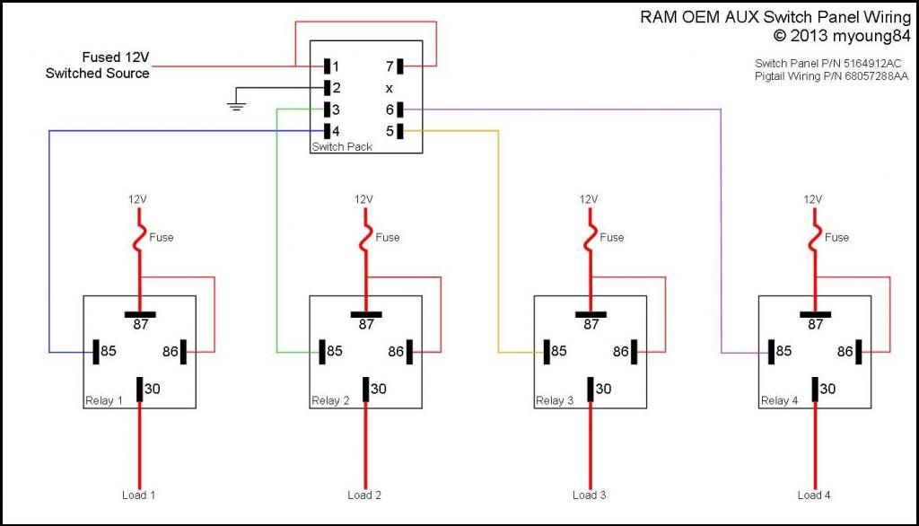
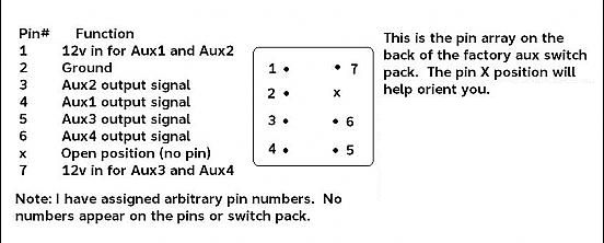
The wire harness will come with the plastic plug and 8 loose wires with metal ends crimped on. You will need to insert 7 of the 8 wires into the plug. Take note of the missing pin in the switch panel and don’t put a wire in that hole. Using the wiring diagram below, start wiring the panel once installed in the dash. Pins 1 and 7 are the 12V inputs. These should both go to a switched 12V source. You can also wire one or both wires to a constant 12V source and this would allow the switches to be operational when the truck is off. I would recommend not doing this since you would have the potential to drain the battery if you leave something on. Pin 2 will go to ground. Finally, pins 3-6 are the ground output wires for buttons 1-4. These will go to one side of the coil on a relay.
All wiring past this point will depend on what you are powering and will vary on each installation. The most common scenario such as lights would require a single relay per button. One of the output wires from the switch panel would go to the coil on the relay, either pin 85 or 86, doesn’t matter. The other side of the coil will go to a 12V source. This can be a constant source directly from the battery or you can jumper off pins 1 and 7 from the switch panel if you are installing the relays inside the truck. For my lights, I ran the output wire from the switch panel under the hood and mounted my relays near the battery.
You have the option of switching the 12V side or the ground side of your lights. I normally switch the 12V side. You would need to run the appropriate size wire from the battery, through a fuse, and to pin 87 on the relay. I will normally make a jumper wire from this pin to the 12V side of the coil on the relay, there’s no need to have separate wires ran. Then run the same size wire from pin 30 to the 12V side of your lights or other load. The ground side of you lights will go directly to ground. If you choose to switch the ground side, you will run your ground wire through pins 87 and 30 and connect the 12V side of your lights directly to the battery, through a fuse. You’ll also need to run a separate 12V wire to the coil of the relay if you choose this method.
Here's a wiring diagram I created with the most common installation. If you have something else you're trying to switch or operate let me know and we'll see if it's possible. I have my LED light bar, rear LED lights, Front Camera, and Locker Bypass on my switches. I'll post the Locker Bypass instructions in the next post.