So I'm the recipient of Flattire's old locker actuator and I finally had some time to do some testing. I wanted to document my findings here in the hopes that someone else dealing with a flashing locker light in the future would have a baseline of information to deal with that might help lead to a more accurate diagnosis. The odd thing is, that in the process of testing, my own rear locker light started flashing and setting a code in the final drive control module (FDCM). I was beginning to suspect that the problem was contagious and that my truck had contracted the disease.
Keep in mind that Flattire's truck is an 2005, which is a pre-CAN computer system, so there is no way to read FDCM data on his truck with a scanner. This makes the situation much more difficult when it comes to diagnosing electronic problems, you have to resort to back probing harnesses with a multimeter to get data and once you have that data there's a drought of information to help you figure out what it means.
I started by doing simple bench tests to check for continuity and resistance.
 Viewed 13616 times")
- Rear Locker Connector for an 05 PW (your wire colors may vary).
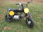
On both the old actuator and the good one that I tested on my truck, the results were the same: When I tested resistance on pins #1 & 4 they both read 1.7 -1.9 ohms. When I applied 12V power and ground to pins #1 & 4 the electro magnet energized and created a magnetic field. Testing the sensor wires (pins #2 & 3) is where it gets weird. On both of them the resistance was 6+ mega ohms and had no significant change when the locker was engaged or disengaged. Pin #2 is a 5V reference voltage from the FDCM/SmartBar into the sensor and pin #3 is the modified voltage returning to the SmartBar based on sensor input. When I measured voltage on pin #3, it was 0.6V when unlocked and 1.4V when locked. The only thing that I didn't do was to apply heat to the old actuator to see if it caused any changes to the readings. However I can tell you that when the electro magnet is energized, after 5+ minutes, it gets almost too warm to touch (130-140º). The way that I tested the "lock/unlock" ability of the old actuator was to plug it into my truck and apply a neodymium magnet to the sensor and read the results on my scanner. Also, the sensor is polarity sensitive to the magnet. Apply the magnet one way and nothing happens, flip the magnet over to the other pole and then you get results.
 Viewed 13616 times")
- Actuator with a small magnet applied to the sensor, to the right of the wires.
Now on to my flashing locker light which developed during the course of testing: The rear locker light would be off after initial startup, but after driving a few miles it would start flashing and then sometimes go off again. If I tried to engage the locker when it was flashing, nothing would happen, but if the light was off, I could engage the locker, but sometimes it would disengage and start flashing. However, last weekend I went wheeling with no flashing light for hours of on and off road driving.
This weekend I hooked up my scanner because it was flashing regularly and this is what I found:
 Viewed 13616 times")
- Rear locker shows "Short to ground" when wiggling connector and unplugged.
I was able to read data while I was driving and as I would go around corners and hit bumps the data would change from "unlocked" to "short to ground" and back again. When I got back to my house there was a code stored and the light was still flashing. I left the engine running and put my scanner under the truck so I could see it. As I wiggled the harness and connector I could change the data so I knew it was a bad connection somewhere. When I unplugged the connector the data continued to read "short to ground". The factory service manual told me to put a jumper wire between pin #2 & 3, when I did that, then it said "short to battery" and wouldn't change as I wiggled the harness.
 Viewed 13616 times")
- Rear locker shows "Short to battery" with pin #2 & 3 jumpered together.
Out of curiosity I opened up the harness loom and discovered that it had been repaired previously (probably got snagged on some sage brush when the BLM owned it). But as it was jumpered and I was wiggling the wiring repair, nothing was changing, so I knew they did a good job fixing it with quality heat shrink.
 Viewed 13616 times")
- BLM repaired harness, still good.
Next I focused my attention on the connector and terminals. The male terminals looked straight and free of corrosion so I used a small dental pick to tighten up the female terminals just a little and then plugged it back in to test it. Apparently that's where the problem was because now I can wiggle the connector and nothing changes on the data.
 Viewed 13616 times")
- Back to normal, "Unlocked".
After this I test drove my truck and exorcized both lockers a couple times, with and without my bypass switch and it all worked as it should.
One other thing I noticed on the FDCM data was four parameters that I hadn't seen before.
 Viewed 13616 times")
- The bottom four lines show "Locked threshold" and "Unlocked threshold".
So the next time it seems like it's taking your lockers forever to engage, maybe it's because you're moving too fast and exceeded the 3 MPH threshold doing the S turn locker dance.
Also, after playing with an actuator on the bench it became apparent to me how important it is that the sensor magnet inside the differential is clean and that the air gap is adjusted correctly. When you're driving down the road towing a trailer and the axle temperature is rising, the magnetic force is getting weaker and the sensor might be telling the SmartBar that it's locked when it really isn't. Read about the
Curie Point on Wikipedia.
Here's the procedure for adjusting the magnet air gap according to the manufacturer and I would favor a tight tolerance if you're having flashing locker light problems.
 Viewed 13616 times")
- Magnet air gap adjustment procedure 24-27.
 Viewed 12863 times")
- My air gap will hold a 5mm hex socket snug.
 Viewed 12863 times")
- A closer view.
So in the end you should have:
- 12V+ at pin #1 when the the locker is engaged.
- 0V at pin #4 when the locker is engaged. (Apparently this is the ground source for both the actuator magnet and sensor)
- Continuity between pins #1 & 4 on the sensor side of the connector with an approximate resistance of 1.8 Ω.
- Approximately 5V always present with the key on at pin #2.
- 0.6V at pin #3, when the connector is plugged in, if your locker is unlocked.
- 1.4V at pin #3, when the connector is plugged in, if your locker is locked.
- 5.0V - 12V at pin #3 would indicate that there is a short in the wiring or sensor to reference voltage or battery+.
- 0.0V at pin #3 would indicate an open circuit or short to ground in the wiring or sensor.
That's the best I can come up with. I hope it helps out someone else in the future.